A pipe can be defined as a tube made of metal, plastic, wood, concrete, or fiberglass. Pipes are used to carry liquids, gases, slurries, or fine particles. A piping system is generally considered to include the complete interconnection of pipes, including in-line components such as pipe fittings and flanges. Pumps, heat exchanges, valves, and tanks are also considered part of the piping system. Piping systems are the arteries of our industrial processes and the contribution of piping systems is essential in an industrialized society. The magnitude of piping required in a typical chemical process plant. Piping systems account for a significant portion of the total plant cost, at times as much as one-third of the total investment. Piping systems arranged within a very confined area can be an added challenge to piping and support engineers. The initial design of a piping system is established by the functional requirements of piping a fluid from one point to another. The detailed design is decided by criteria such as the type of fluid being transported, allowable pressure drop or energy loss, desired velocity, space limitations, process requirements like free drain or requirement of straight run, stress analysis, the temperature of the fluid, etc. The supporting of piping systems requires a significant engineering, design, fabrication, and erection effort. In some cases, special structures (like structural T or inverted L, cantilevers, U portals, pedestals, etc.) must be built solely for the purpose of supporting piping systems. Piping Material
The material to be used for pipe manufacture must be chosen to suit the operating conditions of the piping system. Guidance in selecting the correct material can be obtained from standard piping codes. As an example, the ASME Code for Pressure Piping contains sections on Power Piping, Industrial Gas and Air Piping, Refinery, and Oil Piping, and Refrigeration
Piping Systems.
The objective is to ensure that the material used is entirely safe under the operating conditions of pressure, temperature, corrosion, and erosion expected. Some of the materials most commonly used for power plant piping are discussed in the following sections.
Steel – Steel is the most frequently used material for piping. Forged steel is extensively used for fittings while cast steel is primarily used for special applications. The pipe is manufactured in two main categories – seamless and welded.
Cast Iron – Cast iron has a high resistance to corrosion and to abrasion and is used for ash handling systems, sewage lines, and underground water lines. It is, however, very brittle and is not suitable for most power plant services. It is made in different grades such as grey cast iron, malleable cast iron, and ductile cast iron.
Brass and Copper – Non-ferrous materials such as copper and copper alloys are used in power plants in instrumentation and water services where the temperature is not a prime factor.
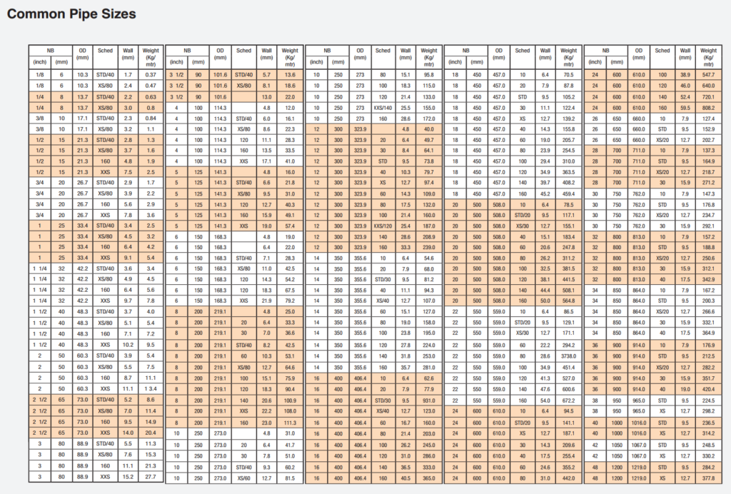
Commercial Pipe Sizes
A commercial pipe is made in standard sizes each having several different wall thicknesses or weights. Up to and including 304.8 mm (12 inches) pipe, the size is expressed as nominal (approximate) inside diameter. Above 304.8 mm, the size is given as the actual outside diameter. All classes of pipe of a given size have the same outside diameter, with the extra thickness for different weights on the inside. For example, if a pipe was designated as 152.4 mm in size this would mean that it has a nominal or approximate inside diameter of 152.4 mm. The outside diameter is 168.28 mm. This is a constant value no matter what the wall thickness is. The actual inside diameter of the pipe will depend upon its wall thickness. For a standard wall thickness, the actual inside diameter of the 152.4 mm pipe is 154.06 mm. For an extra strong wall thickness, the actual inside diameter is 146.34 mm. There are two systems used to designate the various wall thicknesses of different sizes of pipe. The older method lists pipe as standard (S), extra strong (XS), and double extra strong (XXS). The newer method, which is superseding the older method, uses schedule numbers to designate wall thickness. These numbers are 10, 20, 30, 40, 60, 80, 100, 120, 140, and 160. In most sizes of pipe, schedule 40 corresponds to standard, and schedule 80 corresponds to extra strong. Dimensions and the mass in kg/m of different sizes of steel pipe with varying wall thicknesses.
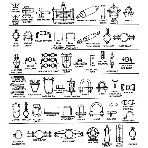
Pipe Fittings A fitting is used in pipe systems to connect straight pipe sections, adapt to different sizes or shapes, and for other purposes, such as regulating (or measuring) fluid flow. Pipe Fittings (especially uncommon types) require money, time, materials, and tools to install, and are an important part of piping and plumbing systems. Valves are technically fittings, but are usually discussed separately. The purposes of the fittings, shown in Fig. 3 may be generally stated as follows: • Elbows – for making angle turns in piping. • Nipples – for making close connections. They are threaded on both ends with the close nipple threaded for its entire length. • Couplings – for connecting two pieces of pipe of the same size in a straight line. • Unions – for providing an easy method for dismantling piping. • Tees and Crosses – for making branch line connections at 90º. • Y-bends – for making branch line connections at 45º. • Return Bends – for reversing direction of a pipe run. • Plugs and Caps – for closing off open pipe ends or fittings. • Bushings – for connecting pipes of different sizes. The male end fits into a coupling and the smaller pipe is then screwed into the female end. The smaller connection may be tapped eccentrically to permit free drainage of water. • Reducers – for reducing pipe size. Has two female connections into which the different sized pipes fit. May also be made with one connection eccentric for free drainage of water.
Methods of Connecting Pipe
There are three general methods used to join or connect lengths of pressure piping.
These are:
1. Screwed Connections.
2. Flanged Connections.
3. Welded Joints.
Each of these methods has certain advantages and disadvantages and each will be discussed in the following sections.
In this method, threads are cut on each end of the pipe and screwed fittings such as unions, couplings, and elbows are used to join the lengths.
This method is generally used for pipe sizes less than 101.6 mm (4 inches) for low and moderate pressures. It has the advantage that the piping can be easily disassembled or assembled. However, the threaded connections are subject to leakage and the strength of the pipe is reduced when threads are cut in the pipe wall.
This method uses flanges at the pipe ends which are bolted together, face to face, usually with a gasket between the two faces.
Flanged connections have the advantage over welded connections of permitting disassembly and are more convenient to assemble and disassemble than screwed connections. In order to prevent leakage at flanged connections, the flange faces, which butt together, would have to be absolutely flat and smooth. While it is theoretically possible to grind the faces to this condition, it is a time-consuming and expensive proposition. Therefore gaskets are usually used between flange faces. Gaskets are made of a comparatively soft material which, when the flanged connection is tightened, will fill in any small depressions in the flange faces and thus prevent leakage.
In this method, the pipe lengths are welded directly to one another and directly to any valves or fittings that may be required. The use of these welded joints for piping has several advantages over the use of screwed connections or flanged connections:
The possibility of leakage is removed with the elimination of screwed or flanged joints. The weight of the piping system is reduced due to the elimination of connecting flanges or fittings. The cost of material and the need for maintenance are reduced with the elimination of flanges and fittings.

• High insulating value.
• Long life.
• Vermin proof.
• Non-corrosive.
• Ability to retain its shape and insulating value when wet.
• Ease of application and installation.
Some of the more common materials used for piping insulation are discussed in the following sections.
• Diatomaceous Silica – This material is bonded with clay and asbestos and is used for temperatures up to 1030ºC.
• Asbestos – Pipe covering sections are molded from asbestos fiber and are used for temperatures up to 650ºC.
• Calcium Silicate – This insulation is made from silica and lime and is suitable for temperatures up to 650ºC.
• Cellular Glass – This material is glass that has been melted and foamed and then molded into pipe-covering forms. It can be used for temperatures up to 430ºC.
• Magnesia (85%) – This material is composed of magnesium carbonate with asbestos fibre. It is available in moulded form for pipe covering and also is supplied in powdered form to be mixed with water to form an insulating cement which is used to cover pipe fittings. Magnesia pipe covering is suitable for service up to 315ºC.
• Glass Fibre – This is glass that has been processed into fibres and then formed into pipe-covering sections that are suitable for temperatures up to 190ºC.
• Plastic Foams – These are plastics that have been processed into a foam during manufacture and then formed into pipe-covering sections. They are available for temperatures as low as -170ºC and as high as 120ºC.
Get A Free Quote For Manufacturing & Fabricating
Contact us at the Industrial nearest to you or submit a business inquiry online.
Contact Us

Common Pipe Sizes